Introduction
This project began when I received a Raspberry Pi 4b as a gift from my lovely girlfriend. I had long sought a similarly capable single-board computer to host a Safing Community Node. After realizing the (many) risks of hosting a public node from my dorm internet, I began researching other uses. After stumbling upon the Raspberry Pi Recovery Kit by Jay Doscher, I had an idea to adapt his design into a mobile Software Defined Radio (SDR)/digital storage device.
Disclaimer
I know that this is far from the most efficient configuration for a RPi-based SDR. I chose this specific route not simply based on efficacy but rather as a way to explore other engineering challenges besides RF.
This article was written with assumption that you have some knowledge of Raspberry Pi computing and RF.
If all you wish is to attempt to build it yourself and have no interest in my journey, you can find the links to all the parts and files at the bottom of each section.
Desired Features
- SDR capable of TX and RX
- 6 hour battery life
- 1 TB of storage
- Ability to run as a storage server
- Ability to run SDR++ locally
- Watertight when closed
- Ability to fit all necessary peripherals inside watertight case
- Portable
3D Modeling
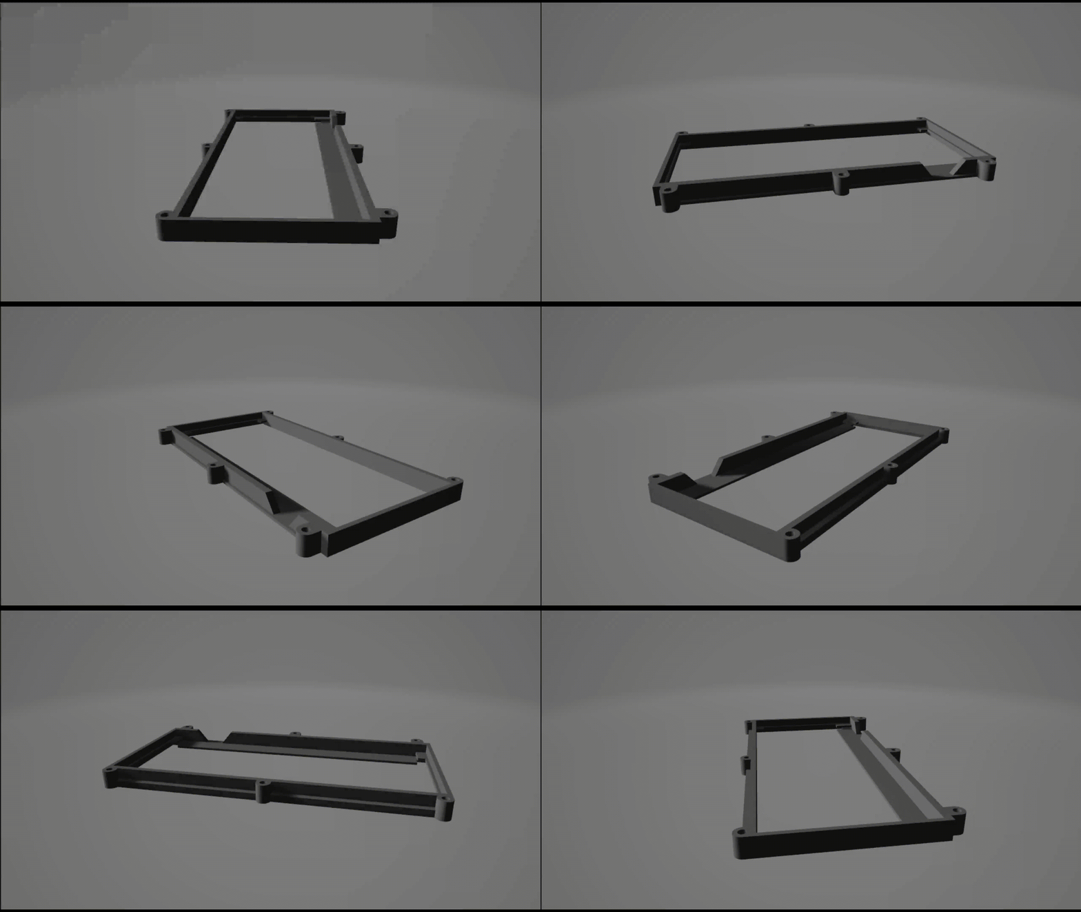
Since the majority of the 3D models were generously provided by Jay Doscher, I only needed to slightly modify the I/O plate and the overall dimensions to fit my purposes. Since my changes were minor, I primarily used Tinkercad to design the models. I used the 3D printing resources at the Billodue Makerspace to FDM print all the parts over the course of two weeks.

I returned to the makerspace regularly for a couple weeks as I prototyped and experimented with the design. After a few iterations I got a model that fit my parts perfectly. Due to my impatience (and lack of funds) I decided to just to ahead and use the final prototype parts, however if you are recreating my process I would highly recommend taking the extra time getting it all to look exactly as you want. As a result, my parts have many scuffs and minor imperfections that could’ve been smoothed out.
It’s important to note that I forgot to post-process my parts, so if you intend to follow this blog as a guide I would recommend you follow one of the many guides online to properly prepare your parts after printing. It can improve the longevity and the aesthetics of your final build.
Part Selection and Research
Power
Finding and ordering the parts was very time consuming. The primary constraint of the project (besides money) was power. The RPi itself has a specification of 5 volts at 3 amps, or 15 watts. Sourcing a powerbank that could provide that power was not too challenging, so I settled on the best deal I could find.
It so happened that the Anker model I chose had a capacity of 20100 mAh, a monstrous amount of power that could power my Pi 4B for a theoretical 6.7 hours at max power draw. I figured that even if I added a couple extra devices to the loop, the battery would be more than sufficient.
If you choose to replicate my design, please get a power bank with a higher voltage. My device in it’s current state cannot boot off of battery because of the increasing power demands of multiple peripherals. My current draw is at an astronomical 5V at 6A, requiring me to use a drill battery if I really wanted to run PoCA remotely.
Network Switch
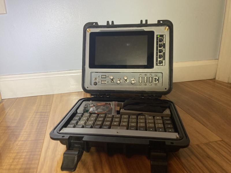
I chose a standard Netgear 4+1 unmanaged switch, primarily because I didn’t want to mess with the tolerances set by Jay Doscher. I went back and forth on whether I needed a switch to match my desired features, but eventually decided that I would rather have extra ports in case I needed to use it as a router in the future. It also just plain looks cool, and seemed to be the best use for the space. Alternatives I explored included:
- Hot-swap hard drive bay
- GPIO Pinout and other I/O
- Storage for a mouse
- Charging dock for my Flipper Zero
- A second pullout display
If I were to rebuild my current design (which I probably will) I may replace the switch, but as of right now I think it fits the device visually and functionally.
Display
The display I chose was the simple and proven Official RPi 7" touchscreen. A touchscreen was key, as including a mouse that would fit inside the keyboard tray was a near impossibility. This was the best option and it fit the original 3D files by Jay Doscher.
Case
The best possible option in terms of quality would have been a Pelican 1300, however it was just not cost effective for me. After doing a bit of digging, a case by Pure Outdoor (AKA Monoprice) matched the size I was looking for (10x9x7 inches). After about six months with this case, I can wholeheartedly recommend it. It feels good to the hands, is relatively lightweight, and shares identical features to a comparable Pelican case.
Keyboard
I could write a long story about why I chose this keyboard, but the simple answer is that it fit. The space constraints for the lid of the case didn’t give me many options in terms of a standard staggered-qwerty layout. This ortho design is a clone from KPRepublic called the BM40, a company that made their own identical PCB design based off another 47-key design called the “Planck”.
Because of the space constraints, I neglected a case and mounted the keyboard by sandwiching the PCB and the plate between 3D printed supports on the keyboard tray. It worked out quite well, but the design could be tweaked a bit to perfect the tolerances.
The switches are Kailh BOX Jade switches, which boast excellent reliability and weather resistance, with a dustproof design. They are a bit loud (clicky), so if you are trying to make a more reasonable choice I can recommend the Jwick, however any MX-style switch should do.
The keycaps are a generic set from Aliexpress. Nothing special.
SDR
The SDR I chose was the full model of the CaribouLite RPi HAT. While it fit the desired specifications in an incredible form factor, I cannot recommend it. It is far from plug-and-play, and is seemingly abandoned by Cariboulabs, the maintainers of the required software. In hindsight, I would have chosen the far more ubiquitous HackRF One by Great Scott Gadgets, a device with similar specifications designed and sold by a seasoned company. If I wanted to buy one of the many clones available for this device, I likely would have even saved a bit of money.
I do appreciate that the CaribouLite is designed specifically for the RPi, but until I can get it to actually function it has no real utility. If I had a bit of a looser budget, I may have opted for a full duplex SDR to experiment with LTE and other communication methods not possible on a half duplex model like the CaribouLite or the HackRF One.
I/O
I used the NKK S1AL and S7AL switches as my power switches. the S7AL functions as an on-off-on switch which I use to toggle between external power and the internal battery, and the three S1AL switches toggle on/off power for my RPi, display, and network switch respectively. I later added my powered USB hub to the toggle for the network switch, which slightly compromises the intention of separate power switches, which was to conserve power in the event I only need to access the Pi over SSH or VNC. The rest of my I/O I purchased on Amazon and had no distinctions over other options besides price.
The barrel jack connecters I included as an option for external power are mounted in two locations: one in the I/O cluster and another on the top of the case, to provide external power if the device was functioning while closed. If you choose to go this route, it’s important to use barrel jack connectors that have an IP rating that supports your needs, because otherwise you compromise the integrity of the case.
Internal components
Besides the RPi itself, I had an external 1 TB M.2 SSD which I was booting off of, a powered USB hub to support the power demands of the SSD, and a large heatsink to cool the Pi.
Final Part List*
- NKK S7AL * 1
- NKK S1AL * 3
- USB-A Right Angle Adapters * 3
- CaribouLite * 1
- RPi 7" Official Display * 1
- Panel Mount DC Barrel Jack * 2
- Panel Mount Aux Passthrough * 1
- Panel Mount USB-A * 5
- Panel Mount Ethernet * 1
- Anker PowerCore 20100 * 1
- NETGEAR 5 Port Unmanaged Switch * 1
- Extendable Dipole Antenna * 2
- 6 Inch Ethernet Patch Cable * 1
- Extended Tip M5 Set Screws * 10
- Assorted M5 Screws * 20-30
- Raspberry Pi 4B * 1
- Raspberry Pi Heatsink * 1
- USB to M.2 Shroud * 1
- 1 TB M.2 SSD * 1
- SABRENT 4 Port Powered USB HUB * 1
- BM40 * 1
- DSA Keycap Set * 1
- Kailh Box Jade * 47
- BM40 Carbon Fiber Plate * 1
- Pure Outdoor Hard Case * 1
Unlisted are various tools, spare parts, and other cabling bits and pieces, none of which are of significant cost.
Assembly
To be included in the next update
Wiring
To be included in the next update
